Abstract– This thesis is a study on control of Brushless DC electric motor (BLDC motors, BL motors) or electronically commutated motors (ECMs, EC motors). BLDC are electronic circuit controlled DC synchronous motors, which produces an AC signal to run the motor. And the input alternating current signal fed to motor, is not a pure sinusoidal, but it may be close to pure sinusoidal waveform actually it is merely a bi-directional current which may be square or triangular or any bi-directional waveform. To control shape the inverter output waveform supplementary electronics detectors are employed to control the amplitude and waveform of input to motor which results in poor percentage of DC bus usage/efficiency and fundamental frequency (i.e. rotor speed). For the rotor a permanent magnet synchronous, a switched reluctance or an induction motor may be employed in a brushless motor. PID which is a mechanism (controller) is used in entire process.
A proportional integral derivative controller (PID controller) is a feedback mechanism type control loop or controller and it very commonly used control systems in industries. A PID controller continuously calculates an error value as the difference between value of a desired and actually measured process variable. A simple yet powerful optimization algorithm is has been applied in this thesis for controlling the speed of BLDC Motor. The concept of this algorithm is that steps and modification are to be done such that new solution moves close and close to best solution and away from worst results for a given problem. In this algorithm we don’t have to set any specific parameter which is requires only the common parameters to control the flow of algorithm are required to be set by user and does not require any specific parameters to be given by user. The performance of PID controller with its parameters being calculated using Jaya algorithm is compared with other PID controller having parameters calculated by use of other recognized algorithms namely PSO and BFO also Ziegler-Nichols classical method. The results have proved the better effectiveness of the proposed algorithm. In this thesis a bird’s eye view of Ziegler-Nichols method, PSO and BFO methods also have been presented. The picture we obtain is that of a technique having high potential of applications, ranging from not only to electrical, electronic and electromagnetic but to other fields also like combinatorial problem solving, biological, medical, graphics, practical computational intelligence applications, image analysis, signal processing even to robotics.
I. Introduction
For industrial purpose we have two kinds of DC motors. The first type is the conventional dc motor in which the flux is produced by the current through the field coil of the stationary pole structure. The second type is the brushless dc motor (BLDC motor) in which the permanent magnet provides the necessary air gap flux instead of the wire-wound field poles. BLDC motor has the advantages better velocity capability, no mechanical commutator, simple structure, higher reliability and free maintenance. Compared to conventional DC motors brushless DC motor superior in terms of: smaller volume, high force, and simple system structure. So BLDC motor is widely applied in high performance drive. In DC brushless motors we have a great advantages in terms of control as in these motors armature flux and field flux can be controlled separately as they are independent of each other. In recent time we have many techniques available in literature as well as in practical to control the performance of linear BLDC for example variable structure control, nonlinear control, adaptive control and optimal control. But all these technique are not easy to implemnt being complex. Compared to all above advanced technique PID controller is much simple to implement as well as quite effective to improve the transient and steady-states performance of all type of systems. Inspire of the simple structure and robustness of “BB-BC” method, optimally tuning gains of PID controllers have been quite easy.
II. Brushless DC Motor
Brushless dc (BLDC) motor is preferred as small horsepower control motors due to their high efficiency, silent operation, compact form, reliability, and low maintenance. It is difficult to control the BLDC motors in variable speed load demand operation. With the development in field of power electronics technology, advancement in semiconductors material in terms of voltage and current ratings, development in VLSI based micro-controllers and microprocessors, in methods of speed control schemes for electric drivers and permanent-magnet brushless electric motor, with these all together it has become possible to design cost-effective, reliable solution for a large range speed drives for different applications.
2.1 Principle of Brushless Linear DC (BLDC) Motor
In Brushless DC electric motor (BLDC motors, BL motors) the operation and speed torque control is carried out using electronic switching control circuits so these motors are also known as electronically commutated motors (ECMs, EC motors). These motors are actually synchronous motor as they run at synchronous speed and synchronous frequency is controlled by power electronics switching circuits. Commentators and brushes are the important part of permanent magnet type DC motors to achieve the commutation. Instead of mechanical commutator and brushes Hall Effect sensors are used in BLDC motors for commutation. In BLDC motors armature coils of fine copper wire are placed on stators, working flux is obtained using permanent magnets which are installed on the rotors. Now current flowing in stators coils generate an armature flux which interact with flux of permanent magnets and thus develop a rotating torque which make the rotor rotating. The position of rotor is sensed by Hall Effect sensors as the commutating signals. As the armature coil is placed on stationary stator and working flux is produced by permanent magnets placed on rotor therefore there is no need of brushes and commutator in BLDC motors. In this dissertation work, study of a three-phase and two-pole BLDC motor is carried out. The kinematics performance of BLDC motors and permanent magnet DC motors nearly same.
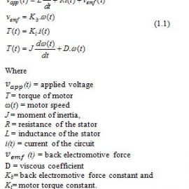
2.2 Mathematical Modeling of BLDC Motor
In permanent magnet DC motors commutation is generally achieved using copper segments made mechanical commentators and carbon brushes. But in case of BLDC motors rotor position sensor based on Hall Effect are adopted instead of mechanical commentators and carbon brushes. In BLDC motors armature coils of fine copper wire are placed on stators, working flux is obtained using permanent magnets which are installed on the rotors. Working flux is rotor permanent magnet flux.
The DC permanent magnet motors and BLDC motors nearly have the same dynamic characteristics. The mathematical modeling equations of BLDC motors can are as follows:
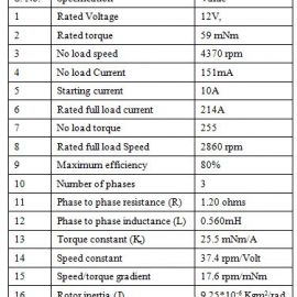
Block diagram of BLDC motorhas been shown in Fig. 3.2(a). From the characteristic equations of the BLDC motor, the control transfer function of motor speed model is derived. The motor parameters for our simulation testing aregiven in table:
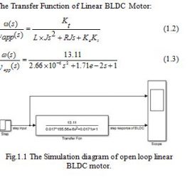
2.3 Step Response of Open Loop BLDC motor
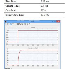
In open loop response of BLDC is slow , large rise time , considerable steady state error, high overshoot. So, a fast acting controller is required to be put in series with motor to improve transient as well as steady state performance.
Selection of Compensator:
The compensators can be any among four type P, PI, PD and PID out of which we have to choose according our requirement based on the following features:
- Steady State Error
- Rise Time
- Maximum Overshoot
- Settling Time
► Proportional controller:
With the increase in proportional gain system steady state error and rise time reduces. But with the proportional gain steady state error can be reduced much but completely cannot be eliminated. Large value of K (proportional gain) may leads to system instability.
► Proportional plus Integral (PI):
Integral term is principally acts to remove or reduce the steady state error but this is done at the price of the speed response of the system. Proportional term used is employed to compensate the lag created by integral term however overall system lags its earlier speed.
► Proportional plus Derivative (PD):
It is principally wont to boost the dynamics of the system and increase the soundness of the system. It has terribly less impact on the steady state error of the system.
► Proportional plus Integral plus Derivative (PID):
It has quick dynamics, zero steady state error and no oscillations with high stability. It’s advantage is that it can be applied to system of any order. Consistent with the benefits offered by PID over alternative we tend to choose PID and here we tend to apply Big-Bang Big-Crunch algorithm to tune the parameters of PID controller for BLDC motor.
Transfer Function of PID Compensator
Consider the continuous-time PID Controller transfer function as shown below,0
= (1.4)
► Fitness function to define we have used integral of time varying standard differences between input and output function in the search or solution space. After each iteration, the values obtained as are compared to the current best solution. In case present value are found to be better means more optimal than previous solution than previous particle are replaced with new one. Otherwise previous are retained as they are. The fitness function returns a numerical value that is used to update the parameters value to the new values, which replace the old values.
III. Big-Bang Big Crunch Algorithm
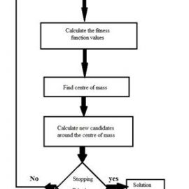
BB-BC algorithm is an heuristic search optimization technique based on evolution of universe as described in Astronomy or Physics. The universe evolution is described in two steps:-
1) Big Bang – explain the distribution of energy in universe randomly in disorder way. On the same concept we generate the solution candidate for any optimization problem to be solved. In this step a large population of solution candidates is generated in search space randomly so actually in this step search space is exploited for feasible solution candidates.
2) Big Crunch – in this phase randomly generated solution candidates called particles here are arranged in an order and best fit solution is chosen among them. So these two steps involve the generation and exploitation of search universes for best fit solution candidate for given problem. Number of solution candidate generated in Big Bang step are continuously reduced in Big crunch step this not only reduces calculation time but also converge quickly towards best fit solution. The concept is that as centre of mass attract other masses towards itself same way best solution candidate will turn direction of convergence from all solution candidate towards it. This is because solution with less error will lie more closer to best fit solution towards which Big crunch get directed. The other features of using variable size of solution candidate avoid the trapping at some local optimum solution with considerable speed.
For determination of controller parameters the steps of the BB–BC algorithm as follows:
- Generate an initial population of N solution candidates randomly is search space in maximum and minimum range.
- Evaluate the value of fitness function for each of the solution candidate. The fitness function has to be designed according to the optimization problem to be solved.
- Find the center of mass according to Equation below. Best fitness individual of each generation can be also chosen as the center of mass instead of using Equation reducing the computation time.
- Calculate new candidates around the center of mass using Equation (9). Notice that the random value added or subtracted to the center of mass decreases as the iterations elapse.
- Return to Step 2 until stopping criteria have been met. Figure 1.3 below shows the flow chart of BB–BC algorithm.
Big Phase Big Crunch Optimization based PID controller
For our BLDC converter, we design the PID controller in BBSC frame as given. We consider the three dimensional search spaces like Kd, Ki and Kp. We define a fitness function in terms of time domain characteristics. Than number of iterations we take for on expected parameters and time of computation. The fitness function is defined as:
Fitness = (rise time + settling time)*10-3 + % overshoot (5.1)
Now, using BB-BC algorithm the controller parameters for our BLDC motor transfer system are obtained as:
Kp = 39.3863, Ki = 0.4623 and Kd = 0.0210
- Result of Linear BLDC Motor system with PID Controller based on BBSC method
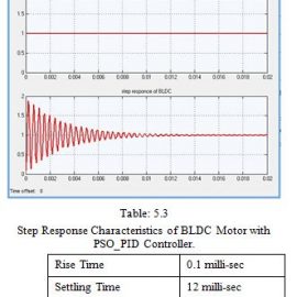
Using particle swarm optimization technique the values of PID parameters and the step response of BLDC motor are obtained as shown in fig. 1.4
IV. Conclusion
We studied BB-BC optimization technique in this section and applied the the same for determination of PID controller parameters for close loop control of BLDC, obtained simulation results, reviewed the performance characteristics of BLDC motor uinsg the same controller. The results are found to be better with BB-BC based controller.
REFERENCES
- 1. Nguyen Thi Thanh Nga al., “ Study on Controlling Brushless DC Motor in Current Control Loop Using DC-Link Current”, American Journal of Engineering Research (AJER), Volume-7, Issue-5, pp-522-528, 2018.
- Abdoalnasir Almabrok et.al., “Fast Tuning of the PID Controller in An HVAC System Using the Big Bang–Big Crunch Algorithm and FPGA Technology”, Algorithms , Pg. 3- 19, Nov. 2018.
- Brajesh Kumar et.al., “Controller Design for Closed Loop Speed Control of BLDC Motor”, International Journal on Electrical Engineering and Informatics – Volume 9, Issue-1, March 2017.
- Mekha M. L and Manju G, “ Speed Control of BLDC Motors Using MRAC”, International Research Journal Of Engineering And Technology (IRJET), Volume: 03 Issue: 06, June-2016.
- P. S. Savalikar and S. D. Joshi, “Speed Control Of Brushless Dc Motor Using PID And Fuzzy-PID Controller In Matlab And Its Comparison”, International Journal of Industrial Electronics and Electrical Engineering,, Volume-4, Issue-7, Jul.-2016.
- P. Selvakumar and T. Kannadasan, “ Studies on BLDC motor for position control using PID-Fuzzy-Neural Network and Anti-windup Controllers”, Australian Journal of Basic and Applied Sciences, Vol. 7(8): Pg. 851-856, 2013.
- Ghaith M. Jaradat and Masri Ayob “Big Bang-Big Crunch Optimization Algorithm to Solve the Course Timetabling Problem”, 10th , IEEE International Conference on Intelligent Systems Design and Applications Pg. 1448 – 1452, 2010.
- Ms. Rashmi Singh and Dr. H.K. Verma, “Big Bang–Big Crunch Optimization Algorithm for Linear Phase Fir Digital Filter Design”, International Journal of Electronics Communication and Computer Engineering, Pg. 74 – 78, Volume 3, Issue 1, 2006.